Introduction
Modern vehicles are equipped with numerous sensors that continuously monitor engine performance, emissions, fuel efficiency, and overall system health. Accessing this data is possible through the On-Board Diagnostics (OBD) protocol, a standardized system implemented in most vehicles manufactured after the mid-1990s. This article explains how OBD works, how to read sensor data, and what is required to build a system that communicates with a vehicle.
What is OBD?
On-Board Diagnostics (OBD) is a vehicle’s self-diagnostic and reporting system. The most widely used version today is OBD-II, which provides a universal interface for retrieving diagnostic trouble codes (DTCs) and real-time sensor data.
OBD-II allows external devices to communicate with a vehicle’s Electronic Control Unit (ECU) and retrieve information such as:
- Engine RPM
- Vehicle speed
- Coolant temperature
- Throttle position
- Fuel system status
- Oxygen sensor readings
How OBD Communication Works
OBD communication is typically done via a 16-pin connector located under the dashboard. A device (scanner, microcontroller, or mobile app) connects to this port and sends requests to the ECU using specific protocols.
Common communication protocols include:
- CAN (Controller Area Network) – most modern vehicles
- ISO 9141-2
- ISO 14230 (KWP2000)
- SAE J1850 (PWM/VPW)
The ECU responds with data encoded in hexadecimal format, which must be decoded according to OBD standards.
Required Hardware
To read OBD data, you typically need:
- OBD-II Adapter
A device such as ELM327 converts OBD signals into a readable format (UART, Bluetooth, Wi-Fi). - Microcontroller or Mobile Device
- Arduino / ESP32 / Raspberry Pi
- Android or iOS device
- Connection Interface
- USB
- Bluetooth
- Wi-Fi
Data Request and Response
OBD uses a request-response model. Each piece of data is identified by a Parameter ID (PID).
Example:
- Request:
010C→ Engine RPM - Response:
41 0C 1A F8
To decode RPM:
RPM = ((A * 256) + B) / 4
RPM = ((0x1A * 256) + 0xF8) / 4 = 1726 RPM
Example Workflow
- Connect OBD adapter to the vehicle
- Pair adapter with your device (Bluetooth/Wi-Fi)
- Send a PID request (e.g.,
010Dfor speed) - Receive ECU response
- Parse and convert the data
- Display or store the result
Software Implementation
In mobile development (e.g., Flutter or Android), communication is typically done via serial/Bluetooth APIs. A simple workflow includes:
- Establishing connection with the adapter
- Sending AT commands to initialize the device
- Sending OBD commands (PIDs)
- Parsing responses
Example initialization commands:
ATZ      // Reset
ATE0     // Echo off
ATL0     // Linefeeds off
ATS0     // Spaces off
ATSP0    // Automatic protocol detection
Use Cases
- Vehicle diagnostics and fault detection
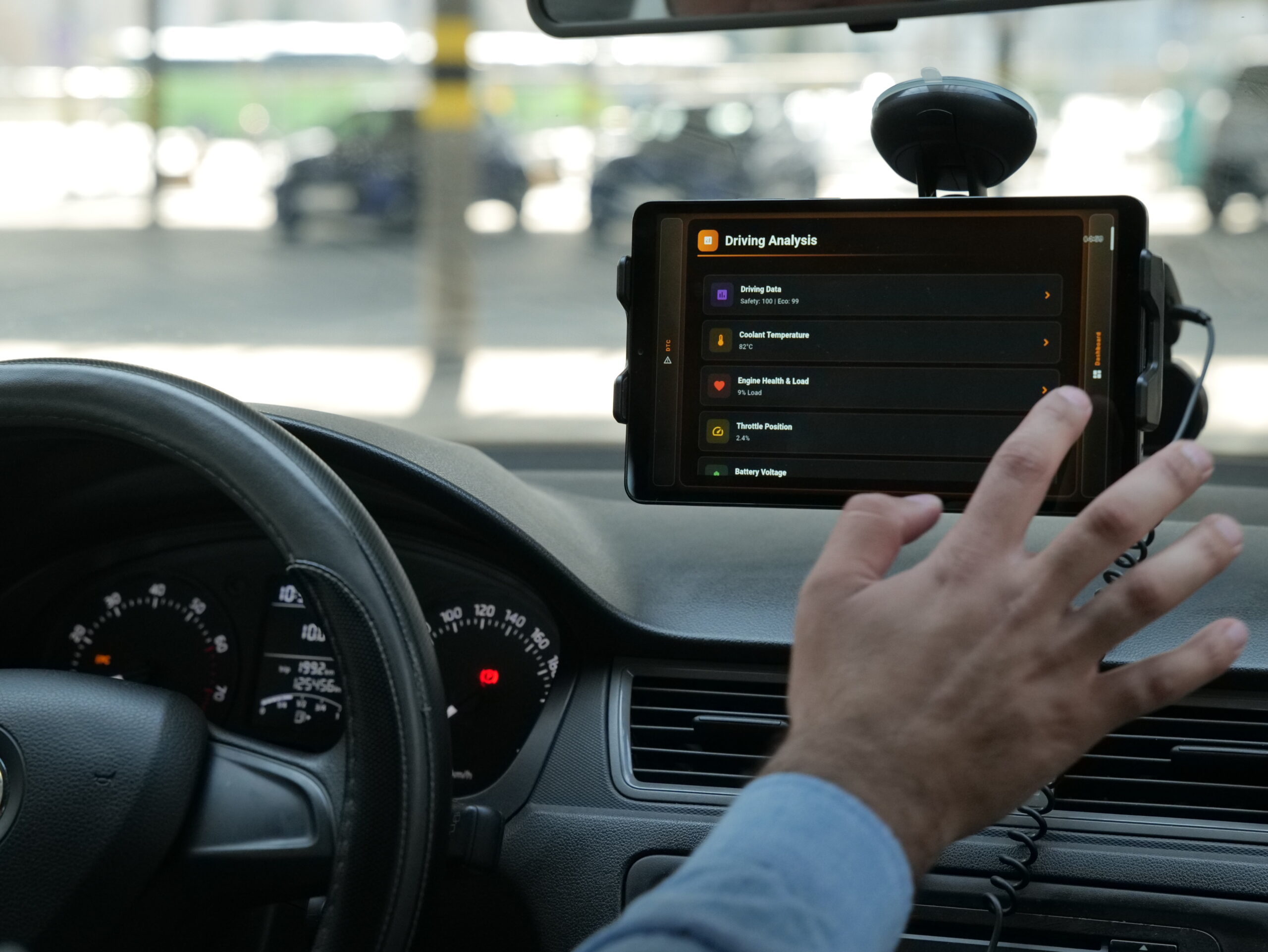
- Real-time dashboards (speed, RPM, temperature)
- Fuel efficiency tracking
- Fleet management systems
- Mobile apps for drivers
Challenges
- Different vehicles may support different PIDs
- Response timing and latency
- Data interpretation requires correct formulas
- Bluetooth connection stability issues
Conclusion
Reading vehicle sensor data using the OBD protocol enables developers to build powerful automotive applications. With the right hardware and understanding of PID-based communication, it is possible to access real-time data from a vehicle’s ECU and transform it into meaningful insights. This technology plays a critical role in diagnostics, performance monitoring, and modern smart vehicle solutions.